Fluidyne engine
is a type of Stirling engine
in which regular moving pistons have been replaced by moving water column.
Since water column always fits the cylinder, machining and fitting the piston to the cylinder is
unnecessary.
Various sources have reported efficiencies of some types of large Fluidyne engines to reach 5%.
Smaller engines are usually much less efficient.
For scientific discussion, Stirling
Engines and Irrigation Pumping paper by C. D. West from 1987 is
highly recommended.
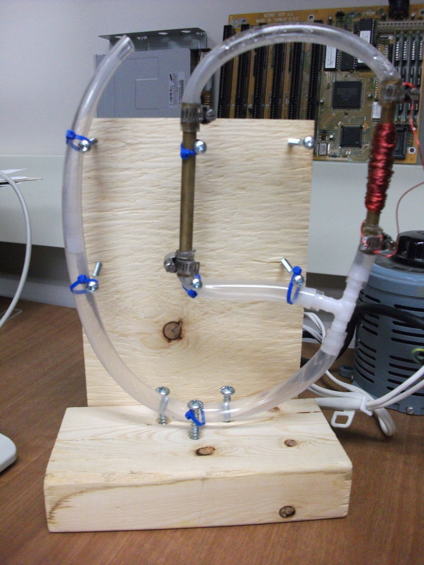
Basic Fluidyne setup with coil wound on top of the hot chamber.
Possible use
Possible use for a Fluidyne is water pumping, using solar concentrators to deliver useful heat
energy to the hot chamber.
Such engine would last for a very long time, cost little and produce no polution.
It is especially attractive for a third world countries for pumping water.
There, fuel and electricity are often lacking, but sunlight is abundant.
Gathering the parts
When I first learned about the Fluidyne engine, during my trials and tribulations with
Stirling engines (which will be detailed elsewhere),
I decided to give it a try with a small model.
I used some small diameter clear bendable tubing that I had, with 8 mm internal diameter.
For hot and cold chambers, I have used bronze (possibly copper, I'm unsure) pipes.
Hot pipe in particular had to be metal because I planned on using fairly high temperatures to
increase engine action and efficiency.
Also I wanted to use induction heating from a coil wound on top of the pipe for precise energy
input measurements, to determine efficiency.
Copper/bronze pipe then served as a single turn transformer secondary.
Initially I used a heat gun instead of induced current for heating the hot chamber pipe.
Since I wanted a precise power efficiency measurement I have switched to
AC induction heating latter.
I had to buy tubing couplers in my local Princess Auto hardware store, but overall the
build was well bellow $20.
AC induction heating turned out to be a bit more difficult than expected.
I suspect that a large proportion of delivered heat energy was actually due to resistive
losses in coil.
This means that regular resistive heater would probably work better, and non metallic chamber
could be used then together with AC or DC power source.
Build
I assembled a rough wooden frame from pieces leftover from previous projects.
Few wood screws were randomly placed to serve as points to tie the tube works to.
Tubes were interconnected through tube couplers, and water was filled in up to about
1/2 of hot/cold metal tubes height.
Clear tubing around metal tubes received additional hose clamps to prevent water from leaking.
Interconnected tubes were tied to wood screws with few plastic tie-wraps.
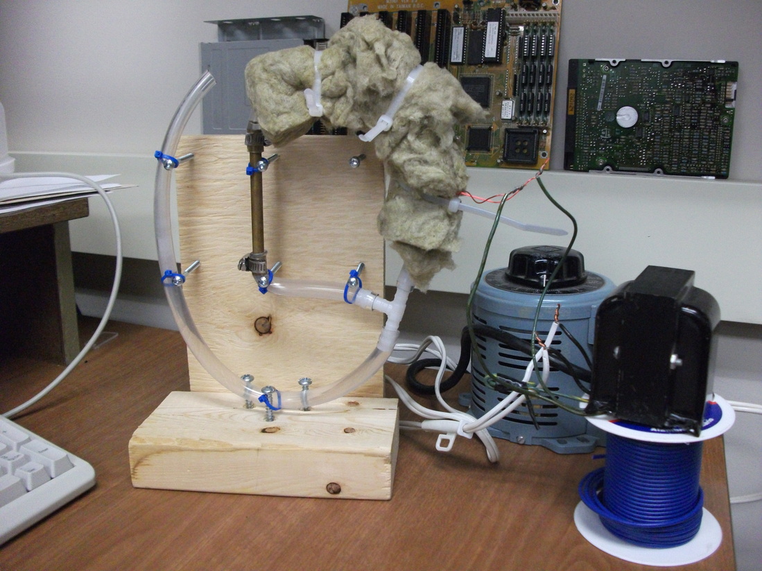
Hot tube is covered with insulation to reduce heat loss.
Also visible: variable autotransformer and regular transformer.
Testing
First I used a heat gun on the hot tube, barely expecting that the thing will work.
After around 45 seconds, water in the open end of the tube started pulsating,
and soon after it began moving up and down more than a centimeter.
It worked as advertised, to my surprise.
After a lot of spilled water and attempted improvements, I learned that sometimes the engine
won't run at all if dimensions (pipe lengths) are incorrectly selected.
With proper dimensions, it will work significantly better than with random sizes.
Also, diameter of tubes, internal air/water volume, temperature of hot and cold chambers all
play a role.
Those were recorded with webcam and deliberate frame dropping to reduce video size,
so quality is not the best. I have also uploaded those videos to Wikimedia Commons some time ago.
First movie shows machine in operation, when heated by hot air gun:
Second movie shows detail of water level fluctuation in leftmost tube.
Problems encountered
Hot chamber pipe would often become so hot that the plastic tube connected to it would melt :)
Tube end was then cut off and reconnected.
This proved to be the weakest part of the whole machine.
Measurements
In the table below are measurements collected with three different power settings.
It can be seen that efficiency was increased markedly with increased power input.
Unfortunately, greater power levels could not be tested due to constant melting of plastic tube
in the spot where it connects to hot chamber pipe.
Power input was found by Pin=Vin*Iin formula, phase shift (cos phi) factor was not measured.
Useful output power was estimated from useful energy delivered in water lifting
Eout=m*g*h, and Pout=Eout/t.
Conclusion
This small model presents intriguing possibilities for further improvements.
Principle is sound and engine works even as a small model, which is often tricky with heat engines.
Larger heat engines always work better than the small ones, because outside surface area
increases as square of dimension, but internal volume increases as a cube of dimension.
To illustrate this point, imagine a cube whose side size is increased three times.
Surface area of the cube will increase nine times (side^2),
but its volume will increase twenty-seven times (side^3).
Next model will be constructed larger and with materials with increased heat resistance,
to provide better data regarding the efficiency for larger power inputs.
In addition, possibility of large increase in power output by using
resonant tube dimensions will be examined when the next model is made.